0 · Recall Warm-up
Answer from memory first. Answers are in the Answer Vault at the bottom.
- Fetch in RTL? from Lesson 2.2.1
- Why can only one register drive a bus at a time? from Lesson 0.2.3
- Booth: the 4-bit multiplier 0111 recodes to? from Lesson 2.1.3
1 · The Hook
🎣
Connect every register to one shared internal bus. It is cheap, but only one value can travel per clock step. Every instruction now becomes a sequence of control steps, each listing which register puts its value on the bus and which registers take it. GATE's datapath questions are exactly this: count the steps.
2 · Predict First
🤔
On a single bus, the ALU needs two operands at once, but the bus carries one value per step. How can the ALU compute R1 + R2?
Make a guess in your head. The answer opens Section 3.
3 · Core Concept
💡
Predict First — the answer
Put R1 on the bus in one step and latch it in a temporary register Y wired to one ALU input; next step put R2 on the bus (the other ALU input) and latch the result in temporary register Z; a third step moves Z to the destination.
The single-bus organisation
- One internal bus connects PC, MDR, IR, R0 … Rn−1, Y and Z.
- MAR only takes from the bus (it drives memory's address lines).
- MDR connects both to the bus and to memory's data lines.
- The ALU's B input comes straight from the bus; its A input comes from a MUX that selects Y or the constant 4 (for PC + 4).
- The ALU result goes into Z, which can later drive the bus.
Control signals
Each register R has Rin (load from the bus at the end of the step) and Rout (drive the bus during the step; tri-state enable). Plus: Read, Write, WMFC, Select4 / SelectY, ALU function (Add, Sub …), End (finish the instruction, start the next fetch).
Rule: in one step, exactly one "out" signal (one value on the bus); any number of "in" signals.
Fetch: 3 steps
| Step | Signals | Meaning |
|---|---|---|
| 1 | PCout, MARin, Read, Select4, Add, Zin | MAR ← PC; start read; Z ← PC + 4 |
| 2 | Zout, PCin, Yin, WMFC | PC ← PC + 4 (and Y ← PC + 4 for branches); wait for memory |
| 3 | MDRout, IRin | IR ← MDR |
Execute ADD R1, R2, R3 (R1 ← R2 + R3): 3 more steps
| Step | Signals |
|---|---|
| 4 | R2out, Yin |
| 5 | R3out, SelectY, Add, Zin |
| 6 | Zout, R1in, End |
Total 6 steps. The execute phase of any register–register ALU instruction takes 3 steps on this bus.
Execute ADD R1, (R3) (R1 ← R1 + M[R3]): 4 more steps
| Step | Signals |
|---|---|
| 4 | R3out, MARin, Read |
| 5 | R1out, Yin, WMFC |
| 6 | MDRout, SelectY, Add, Zin |
| 7 | Zout, R1in, End |
Step 5 does useful work (moving R1 into Y) while memory is busy.
Execute an unconditional branch (PC-relative)
After the fetch, Y already holds the updated PC (step 2).
| Step | Signals |
|---|---|
| 4 | Offset-field-of-IRout, SelectY, Add, Zin |
| 5 | Zout, PCin, End |
For a conditional branch, step 4 checks the flag: if the condition is false, it issues End and the instruction is over.
Counting rules of thumb
- One bus transfer per step; one ALU operation needs its first operand in Y beforehand and its result taken from Z afterwards.
- A memory read needs a step to load MAR (and issue Read), then the data is usable from MDR after MFC.
- Overlap useful transfers with WMFC waits.
4 · Visual
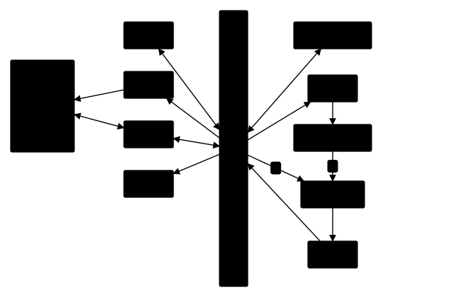
Single-bus datapath: one value per step on the bus; Y holds the first ALU operand, Z the result.
5 · Worked Examples
Example 1 Easy
How many control steps does the execute phase of MOV R1, R2 (R1 ← R2) take on the single bus?
Solution
1: R2out, R1in, End.
Example 2 Medium
How many steps (fetch included) does LOAD R1, (R2) (R1 ← M[R2]) take?
Solution
Fetch 3; then: 4: R2out, MARin, Read; 5: WMFC; 6: MDRout, R1in, End. Total 6. (Step 5 only waits; there is nothing else to do.)
Example 3 GATE
Execute SUB R1, R2 meaning R1 ← R1 − R2 on the single bus. List the steps after the fetch.
Solution
4: R1out, Yin; 5: R2out, SelectY, Sub, Zin; 6: Zout, R1in, End. Three steps (the ALU computes Y − bus).
6 · GATE Traps
⚠️
- Only one "out" per step; several "ins" are fine.
- The ALU result cannot go straight to a register: it passes through Z.
- Fetch takes 3 steps on this bus, and PC + 4 is computed by the ALU (Select4).
- A memory read cannot use MDR's data in the step that issues Read.
7 · Memory Hook
🧠
"One out, many in; Y before, Z after."
8 · Connect the Dots
Lesson 2.2.1 wrote the transfers; this lesson packed them onto one bus: 3 steps to fetch, 3 for a register add, 4 for an add with a memory operand. Next: give the CPU two or three buses and watch the step counts drop.
9 · Self-Test
GATE format. Try every question before opening the vault.
Q1NAT1 markRegister ADD
On the single-bus datapath, how many control steps does the execute phase of ADD R1, R2, R3 take?
Numerical answer: ________
Q2NAT2 marksMemory-operand ADD
How many control steps in total (fetch included) for ADD R1, (R3) (R1 ← R1 + M[R3])?
Numerical answer: ________
Q3MCQ1 markWhy Y
The temporary register Y is needed because:
- (A) the PC must be saved during a branch
- (B) the bus can carry only one value per step, but the ALU needs two operands
- (C) MAR cannot drive the bus
- (D) memory is slower than registers
Q4MSQ2 marksSame-step signals
Which signal sets can legally appear together in one step?
- (A) PCout, MARin, Read, Select4, Add, Zin
- (B) R1out, R2out, Yin
- (C) Zout, PCin, Yin, WMFC
- (D) MDRout, IRin, R5in
Q5NAT2 marksSteps for a store
STORE R2, (R3) means M[R3] ← R2. On the single bus, a write needs the address in MAR and the data in MDR, then one WMFC step. How many steps does the execute phase take?
Numerical answer: ________
10 · Rule Card
- Single bus: one out per step; MAR in-only; ALU A ← MUX(Y, 4), B ← bus; result → Z.
- Fetch: PCout, MARin, Read, Select4, Add, Zin | Zout, PCin, Yin, WMFC | MDRout, IRin (3 steps).
- Register ALU op execute: 3 steps (Y ← src1; Z ← Y op src2; dest ← Z).
- Memory operand: + MAR load / Read step; overlap work with WMFC.
- Branch: offset + Y (PC) → Z → PC: 2 steps.
11 · Concept Ledger
Unlocked in this lesson. From here on, these terms may be used.
single-bus organisationcontrol stepRin / Rout signalsRead, Write, WMFC, EndSelect4 / SelectYtemporary registers Y and Zone-driver-per-step rule
12 · Answer Vault
Answer Vault
Try the questions first. Open when you are ready to check.
Recall Warm-up
- MAR ← PC; MDR ← M[MAR], PC ← PC + 4; IR ← MDR.
- Two drivers cause a bus conflict (tri-state, one enabled).
- +1 0 0 −1.
Self-Test
Q1 Answer: 31 mark
Y ← R2; Z ← Y + R3; R1 ← Z.
Re-read: Lesson 2.2.2 — Single-bus datapath: control signals and micro-operation steps for fetch and execute
Q2 Answer: 72 marks
Fetch 3 + execute 4.
Re-read: Lesson 2.2.2 — Single-bus datapath: control signals and micro-operation steps for fetch and execute
Q3 Answer: (B)1 mark
Y holds one operand while the bus carries the other.
- (A) is wrong: Y does hold PC + 4 for branches, but that is a reuse, not the reason.
- (C) is wrong: True but not why Y exists.
- (D) is wrong: Unrelated to Y.
Re-read: Lesson 2.2.2 — Single-bus datapath: control signals and micro-operation steps for fetch and execute
Q4 Answer: (A) (C) (D)2 marks
B puts two values on one bus. D is legal (one out, two ins), though unusual.
- (B) is wrong: Two "out" signals in one step.
Re-read: Lesson 2.2.2 — Single-bus datapath: control signals and micro-operation steps for fetch and execute
Q5 Answer: 32 marks
4: R3out, MARin · 5: R2out, MDRin, Write · 6: WMFC, End. Steps 4 and 5 cannot merge: each needs its own "out".
Re-read: Lesson 2.2.2 — Single-bus datapath: control signals and micro-operation steps for fetch and execute