0 · Recall Warm-up
Answer from memory first. Answers are in the Answer Vault at the bottom.
- Settling time of an n-stage ripple counter? from Lesson 6.2.2
- JK excitation for 0 → 1? from Lesson 6.1.2
- Minimal SOP method for 4 variables? from Lesson 4.1.1
1 · The Hook
🎣
A synchronous counter gives every flip-flop the same clock, so all bits change together: fast and glitch-free. The price is a little logic in front of each flip-flop. The same method designs a counter for any sequence, such as a traffic light's 0 → 1 → 3 → 7 → 6 → 4. GATE asks both directions: "here is the circuit, what sequence does it count?" and "design a counter for this sequence".
2 · Predict First
🤔
A 2-bit synchronous counter has T₀ = 1 and T₁ = Q₀ (T flip-flops). Starting from Q₁Q₀ = 00, what are the next four states?
Make a guess in your head. The answer opens Section 3.
3 · Core Concept
💡
Predict First — the answer
01, 10, 11, 00: a binary up counter (Q₁ toggles exactly when Q₀ is 1).
🗣️
In plain words
To analyse a synchronous circuit: for each present state, compute the flip-flop inputs from the given equations, then each flip-flop's next value; follow the arrows to find the sequence. To design one: write each state's next state, use the excitation table to find what each flip-flop's inputs must be, and minimise those inputs with K-maps.
1. Binary up counter with T flip-flops
A bit toggles when all lower bits are 1: T₀ = 1, T₁ = Q₀, T₂ = Q₁Q₀, T₃ = Q₂Q₁Q₀. All flip-flops share the clock; delay per count = t_pd + one AND + t_su, independent of n (with the AND chain computed in parallel).
2. Analysis procedure
- Write the flip-flop input equations.
- For every present state, compute the inputs and the next state (characteristic equations).
- Draw the state sequence; check what the unused states do. If every unused state eventually enters the main cycle, the counter is self-starting; otherwise it can lock out.
Example (JK flip-flops): J₁ = Q₀, K₁ = 1, J₀ = Q₁', K₀ = 1.
| Q₁Q₀ | J₁K₁ | J₀K₀ | Next |
|---|---|---|---|
| 00 | 0 1 | 1 1 | 01 |
| 01 | 1 1 | 1 1 | 10 |
| 10 | 0 1 | 0 1 | 00 |
| 11 | 1 1 | 0 1 | 00 |
Sequence 00 → 01 → 10 → 00: a mod-3 counter; the unused state 11 goes to 00, so it is self-starting.
3. Design procedure
- List the sequence; draw the state table (present → next).
- Choose flip-flops; from the excitation table write each flip-flop's inputs for every row (unused states → don't-cares).
- K-map each input; draw the circuit; check the unused states.
Example: sequence 000 → 001 → 011 → 111 → 110 → 100 → 000 (Q₂Q₁Q₀) with D flip-flops. The next state is read off directly:
- D₂ = next Q₂ = Q₁, D₁ = next Q₁ = Q₀, D₀ = next Q₀ = Q₂' (a Johnson counter in disguise).
- Unused states: 010 → 101 → 010 … a separate cycle: this design is not self-starting.
4. Speed
All flip-flops switch together; f_max = 1/(t_pd + t_comb + t_su), the same as Lesson 6.1.3, no ripple.
4 · Visual
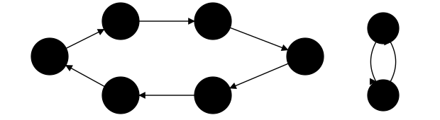
The designed sequence (blue) and the two unused states (gray), which cycle between themselves: the counter is not self-starting.
5 · Worked Examples
Example 1 Easy
In a synchronous 4-bit binary up counter built from T flip-flops, what is T₃?
Solution
Q₂Q₁Q₀.
Example 2 Medium
For the mod-3 JK example above, what state follows 11?
Solution
00 (J₁K₁ = 11 toggles Q₁ to 0; J₀K₀ = 01 resets Q₀).
Example 3 GATE
A 3-bit counter uses D flip-flops with D₂ = Q₁, D₁ = Q₀, D₀ = Q₂'. How many distinct states does it pass through starting from 000?
Solution
000, 001, 011, 111, 110, 100 → 6.
6 · GATE Traps
⚠️
- Synchronous: one common clock; ripple: chained clocks.
- In design, unused states are don't-cares for the input K-maps, but always check where they lead.
- With D flip-flops the inputs are just the next-state bits; with JK/T use the excitation table.
- A counter that never leaves an unused cycle is not self-starting (lock-out).
7 · Memory Hook
🧠
"Analyse: equations → next state → follow arrows. Design: sequence → excitation → K-maps. Check the unused states."
8 · Connect the Dots
A counter is a state machine whose next state ignores outside inputs. The last lesson adds inputs and outputs: Mealy and Moore machines, sequence detectors, and how to remove redundant states.
9 · Self-Test
GATE format. Try every question before opening the vault.
Q1MCQ1 markUp counter
In a synchronous binary up counter made of T flip-flops, flip-flop i toggles when:
- (A) every clock edge
- (B) all lower bits are 1
- (C) the bit just below is 0
- (D) all lower bits are 0
Q2NAT2 marksAnalysis
JK flip-flops with J₁ = Q₀, K₁ = 1, J₀ = Q₁', K₀ = 1 start at 00. How many different states does the counter visit (including 00)?
Numerical answer: ________
Q3MCQ2 marksSelf-starting
The counter with D₂ = Q₁, D₁ = Q₀, D₀ = Q₂' is started in state 010. What happens?
- (A) It enters the main cycle after one clock
- (B) It goes to 000
- (C) It alternates between 010 and 101 for ever
- (D) It stops at 010
Q4NAT2 marksDesign
A synchronous counter must cycle through 6 distinct states. Minimum number of flip-flops?
Numerical answer: ________
Q5MCQ1 markSpeed
Compared with a ripple counter of the same size, a synchronous counter:
- (A) settles in about one flip-flop delay plus logic, independent of the number of stages
- (B) needs no clock
- (C) is always slower
- (D) needs no flip-flops
10 · Rule Card
- Synchronous counter: one clock for all flip-flops. Up counter (T): T₀ = 1, Tᵢ = Qᵢ₋₁ ⋯ Q₀.
- Analysis: input equations → next states → sequence; check unused states (self-starting vs lock-out).
- Design: state table → excitation table → K-maps (unused = don't care) → circuit → check unused states.
- With D flip-flops, Dᵢ = next Qᵢ.
11 · Concept Ledger
Unlocked in this lesson. From here on, these terms may be used.
synchronous counterbinary up counter with T flip-flopsanalysis of a counterstate tablestate sequenceunused statesself-starting counterlock-outcounter design proceduredesigning with D, T and JK flip-flops
12 · Answer Vault
Answer Vault
Try the questions first. Open when you are ready to check.
Recall Warm-up
- n × t_pd.
- J = 1, K = x.
- A Karnaugh map.
Self-Test
Q1 Answer: (B)1 mark
T₂ = Q₁Q₀, etc.
- (A) is wrong: Only bit 0 does.
- (C) is wrong: No.
- (D) is wrong: That is a down counter's rule.
Re-read: Lesson 6.2.3 — Synchronous counters: analysis and design
Q2 Answer: 32 marks
00, 01, 10.
Re-read: Lesson 6.2.3 — Synchronous counters: analysis and design
Q3 Answer: (C)2 marks
010 → 101 → 010: a lock-out cycle.
- (A) is wrong: It never reaches the main cycle.
- (B) is wrong: No.
- (D) is wrong: It changes.
Re-read: Lesson 6.2.3 — Synchronous counters: analysis and design
Q4 Answer: 32 marks
2³ = 8 ≥ 6.
Re-read: Lesson 6.2.3 — Synchronous counters: analysis and design
Q5 Answer: (A)1 mark
All stages switch together.
- (B) is wrong: No.
- (C) is wrong: Usually faster.
- (D) is wrong: No.
Re-read: Lesson 6.2.3 — Synchronous counters: analysis and design